Zhixing Machine Zhixing Machine

Top 10 Milling and Notching Tips for Different Profiles?

Time:2026-11-22 Author:Oliver
0%

Milling and notching can look straightforward until the profile changes. A flat bar, thin tube, and wide channel each sit differently against a fence or fixture. Their edges also respond differently to cutting pressure. One setup rarely suits every shape.

These differences affect more than appearance. A poorly supported workpiece may vibrate, shift, or develop a rough edge. Even a small notch can weaken a narrow section if its position or depth is wrong. Careful setup matters.

How to handle different profile shapes in milling and notching depends on matching the method to the material and geometry. Check the drawing, confirm the profile dimensions, and identify the surfaces that need support before cutting. A square tube may need firm clamping on two faces, while an open channel may require a backing block to prevent flexing. Use a cutter suited to the material, and make a test cut when tolerances are tight.

For repeat work, record the fixture position, tool choice, and cutting settings. Inspect the first part with suitable measuring tools, then check for burrs, heat marks, or deformation. Still, a documented setup is not a guarantee; worn tools and material variation can change results. Recheck when conditions change.

The ten tips in this guide focus on practical choices for common profiles, from clamping and alignment to cut order and finishing. Adapt them to your machine and workpiece. Good results start with a stable setup.
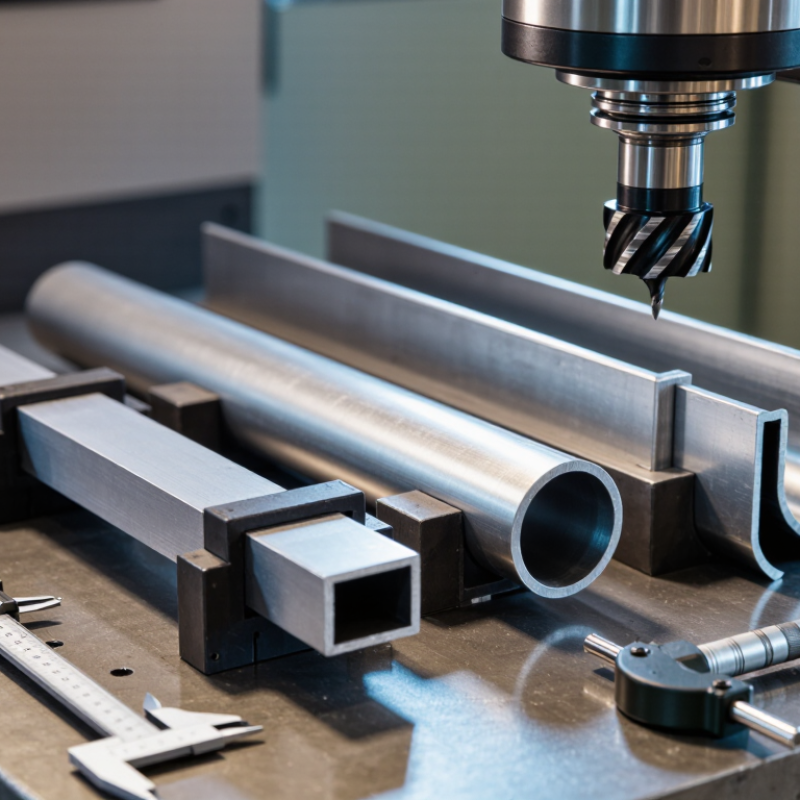
Top 10 Milling and Notching Tips for Different Profiles?

Understanding Profile Types and Milling or Notching Requirements

A profile’s cross-section determines how it should be held, cut, and checked. Solid bars can usually tolerate firm clamping, but deep milling still needs support to limit chatter. Hollow sections need care: excessive clamping pressure can dent a wall before the cutter reaches it. Thin-wall extrusions may also flex under tool load, so smaller passes and close support often produce a cleaner edge. Angle and channel profiles bring another challenge. Their open sides can twist or vibrate if the fixture does not contact them evenly. Small details matter. A slight shift can change a notch’s fit.

Milling removes material from a face or edge; notching creates a localized cut to clear another member or fitting. The required clearance depends on wall thickness, joint angle, assembly sequence, and any later coating. Check the drawing’s datums and tolerances before choosing a setup. Then verify that the cutter can reach the full cut without striking an adjacent wall. On a first article, inspect the opening with calipers and try a dry fit. It may look right on screen and still bind in assembly. That is useful feedback, not a reason to force the parts together. Record the adjustment, and confirm it against the design intent before repeating the cut.

Choosing Tools and Setups for Different Material Profiles

Choosing tools and setups starts with the profile, not just the alloy name. A 6061-T6 plate can tolerate more aggressive engagement than a thin-walled extrusion, which may flex under clamping pressure. The Aluminum Association’s 2020 Aluminum Design Manual lists a minimum yield strength of 240 MPa for common 6061-T6 product forms. Still, strength alone does not predict chatter or burrs.

For flat profiles, use a short tool overhang and support the work close to the cut. On hollow sections, spread clamping force with soft jaws or shaped backing blocks. A narrow notch often benefits from a smaller cutter and lighter radial engagement; check chip clearance before increasing feed. For 304 stainless, ASTM A240/A240M specifies a minimum tensile strength of 515 MPa. Keep the tool sharp, avoid dwelling, and test a conservative cut first. Heat builds quickly.

Round stock needs firm, concentric holding; irregular profiles may need a custom nest. Match flute count and chip space to the material and cut depth, then verify runout and workholding. ISO 8688-2 provides a standardized method for evaluating milling tool life, useful when comparing trial setups. Record sound, edge wear, and burr size—not just cycle time. A setup can look rigid on paper and still chatter. That judgment deserves a second check.

Top 10 Milling and Notching Tips for Different Profiles: Choosing Tools and Setups

# Material Profile Typical Operation Tool Choice Setup and Workholding Practical Tip
1 Solid bar or rectangular stock Slot milling, shoulder milling, or end notching End mill suited to the material and cut; use a roughing tool for heavier stock removal when appropriate Clamp the stock firmly in a vise or fixture, support overhang, and keep the tool engagement consistent Face or locate a reference surface first. Check that the workpiece is seated against the fixed jaw before machining.
2 Round tube Cross-slotting, fish-mouth notching, or end trimming End mill or profile-matched notching cutter selected for the required notch geometry Use a V-block, shaped nest, or dedicated fixture to prevent rolling; support the tube close to the cut Confirm the tube centerline and rotation before cutting. Thin walls can deform under clamping pressure.
3 Square or rectangular hollow section Corner notching, slotting, or access-window milling End mill for slots and openings; a suitable saw or purpose-built cutter may be more efficient for straight separations Clamp across supported faces and use an internal support or close-fitting nest where wall collapse is a concern Deburr the inner and outer edges after cutting, and check that the opposite wall has not been unintentionally marked or cut.
4 Angle section Leg notching, slotting, or end trimming End mill for controlled local cuts; choose flute geometry and coating appropriate to the work material Support both legs so the angle cannot rock; use parallels or a formed fixture to establish a repeatable datum Check for leg distortion after clamping. Avoid unsupported cuts near the free edge, where vibration and burrs are more likely.
5 Channel section Web slots, flange reliefs, or end notches End mill for localized features; select reach and diameter to clear the channel flanges Support the web and both flanges, and restrain the section against twisting or springing Verify tool clearance through the full toolpath, especially at the channel lips and internal corners.
6 I-beam or wide-flange section Flange or web slotting and local relief cuts Rigid milling cutter appropriate to the machine, feature size, and material; use a smaller end mill only where access requires it Use a stable fixture that supports the section near the cut and prevents rotation; confirm machine capacity for the workpiece Plan tool access and chip evacuation before machining. Large sections may require multiple setups to reach different faces.
7 Thin sheet or plate edge Edge notching, open slots, or shallow edge reliefs Sharp end mill or a suitable sheet-cutting process, depending on thickness, geometry, and edge-quality requirements Use close backing and broad, even clamping; minimize unsupported material around the cut Thin material can lift or chatter. Reduce unsupported span and check for sharp burrs before handling.
8 Thin-wall aluminum extrusion Slotting, pocketing, or end notching Sharp, polished-flute cutter designed for aluminum; avoid a tool geometry that encourages chip packing Use a profile-matched fixture and clamp on supported areas without crushing hollow chambers Clear chips frequently and use a suitable lubricant or coolant where permitted. Check for built-up material on the cutting edge.
9 Stainless-steel profile Slots, relief cuts, or localized notches Rigid, sharp carbide or other material-appropriate tooling with geometry intended for stainless steel Keep the setup rigid, minimize tool overhang, and secure the profile against movement throughout the cut Avoid dwelling or rubbing at the cut. Use cutting conditions recommended for the specific stainless grade and maintain steady tool engagement.
10 Mixed or custom structural profile Compound notch, intersecting slots, or features across multiple faces Choose the cutter for the tightest feature and verify that its reach, diameter, and corner radius suit the geometry Use a dedicated nest or indexed fixture; define datums that can be reproduced across setups Make a simulation or trial cut on scrap when possible. Inspect critical dimensions and fit before repeating the operation.

General guidance: cutting conditions depend on the exact alloy, tool geometry, machine rigidity, and workholding. Follow the tooling and machine guidance for the specific job, secure the workpiece, wear appropriate protective equipment, and remove chips only when the machine is safely stopped.

Preparing Profiles for Accurate and Safe Machining

Preparing Profiles for Accurate and Safe Machining

Accurate milling and notching begin before the cutter starts. Identify each profile’s true datum, then mark the notch position from that reference—not from a rough, uneven edge. Check the drawing against the actual workpiece, especially where wall thickness or extrusion shape varies. A small mismatch can shift the cut and weaken a thin section. Remove burrs, oil, and loose chips so the profile seats flat against its supports. It sounds basic. But it is easy to overlook.

Support long or hollow profiles close to the cutting area, without crushing them. Clamp firmly, then check for movement by hand before machining. Confirm tool reach, cutter condition, and clearance around clamps; a tool that barely clears can still collide under load. The U.S. Bureau of Labor Statistics reported a 2.8 recordable-injury rate per 100 full-time workers in manufacturing in 2023, in its Employer-Reported Workplace Injuries and Illnesses report. That figure covers manufacturing broadly, not milling alone, but it reinforces the need for guarding and controlled setups. Keep guards in place, clear chips with a brush only after motion stops, and verify the first cut with a suitable measuring tool.

A setup can look perfect and still be wrong. Check it again.

Applying Milling and Notching Techniques to Common Profiles

Milling and notching common profiles works best when the setup matches the material and cross-section. For square tubing, clamp the workpiece close to the cut to limit vibration, then mill a shallow locating flat before making a deeper notch. Check the wall thickness first. Thin walls can crush under excessive clamping force.

For angle and channel profiles, support both legs so the tool does not pull the section out of alignment. A small cutter can reach inside corners, but it may leave a rougher finish and take longer. On round tube, use a shaped nest or V-block and mark the centerline clearly. Rotate the tube only after checking that the next cut remains square to the first. Small errors show.

Extruded profiles often have ribs or hollow chambers that change the best cutting path. Inspect the section, then place the notch where enough material remains to carry the load. Use light passes near thin webs, and deburr both faces without rounding away a critical edge. Measure the first part against the drawing before repeating the setup. I once trusted a clean-looking notch too soon; a quick fit check would have caught the interference. Keep a record of cutter size, feed, and clamping position, since the same profile can behave differently with another alloy or wall thickness.

Checking Finished Profiles for Fit, Accuracy, and Surface Quality

Top 10 Milling and Notching Tips for Different Profiles?

Checking Finished Profiles for Fit, Accuracy, and Surface Quality

A clean-looking profile can still fail during assembly. After milling or notching, remove burrs without rounding the locating edges. Measure the critical width, notch depth, and angle at several points, including near both ends. A caliper may miss a slight taper; use a suitable go/no-go gauge or inspect the mating part when the fit is critical. Small errors compound. Keep parts and measuring tools at a stable temperature, and record the instrument’s resolution.

Use tolerances tied to the drawing and function, not a generic “tight” target. ISO 286-1:2010 lists an IT7 tolerance width of 18 μm for basic sizes over 10 mm up to 18 mm. That is a reference grade, not an automatic acceptance limit for every profile. For surface checks, ISO 21920-2:2021 defines profile-texture parameters; specify the required parameter and limit on the drawing. Inspect bearing faces under consistent lighting, and check for chatter marks, torn edges, or raised burrs that can distort contact. A rough patch can hide in a small notch. I still find visual checks easy to rush, so pair them with recorded measurements and a trial fit.

FAQS

How should I mark a notch position accurately?

Find the profile’s true datum and measure from it, not from a rough edge. Check the drawing against the actual workpiece.

What should I clean before clamping a profile?

Remove burrs, oil, and loose chips so the profile sits flat on its supports. Small debris can tilt the setup.

How can I stop a long profile from vibrating?

Support it near the cutting area and clamp firmly without crushing it. Check for movement by hand. It matters.

How should I clamp thin-walled square tubing?

Check the wall thickness first. Clamp close to the cut, then make a shallow locating flat before the deeper notch.

What support works for round tubing?

Use a shaped nest or V-block and mark the centerline clearly. Check alignment before rotating the tube for another cut.

How should I machine angle or channel profiles?

Support both legs to help prevent the tool from pulling the section out of alignment. A small cutter may reach inner corners, but can leave a rougher finish.

What should I consider when notching an extruded profile?

Inspect its ribs and hollow chambers. Place the notch where enough material remains, and use light passes near thin webs.

What checks should I make before repeating a setup?

Measure the first part against the drawing and check its fit. I still sometimes trust a neat-looking notch too quickly. Record cutter size, feed, and clamping position.

Conclusion

This guide explains how to adapt milling and notching methods to different profile shapes, including tubes, channels, angles, and other sections. How to handle different profile shapes in milling and notching begins with identifying each profile’s geometry, material, and intended fit, then selecting suitable cutters, supports, and machine settings. Careful setup helps keep the workpiece stable and reduces the risk of inaccurate cuts or surface damage.

Before machining, measure and mark each profile clearly, secure it firmly, and check that the cutting path is unobstructed. Use techniques suited to the shape, adjusting feed, alignment, and support as needed to maintain clean edges and consistent dimensions. After milling or notching, inspect the finished profile for fit, accuracy, burrs, and surface quality. These checks help identify issues early and ensure the parts align properly during assembly.

Oliver

Oliver

Oliver is a seasoned marketing professional with a wealth of expertise in driving brand awareness and engagement. With a deep understanding of our company's product offerings, he consistently delivers high-quality content that enriches our professional blog. His insights not only shed light on......