Zhixing Machine
How to improve processing speed without losing precision is not a contest to push every feed rate higher. It is a controlled effort to remove wasted motion while protecting the dimensions, finish, and repeatability the part requires. A faster cut can look impressive on the machine screen, yet tool wear, chatter, heat, or a poorly secured workpiece may quietly undermine the result. Small changes matter. A worn insert, a long tool overhang, or an unnecessary tool change can add seconds—and risk—across a production run.
Shigeo Shingo, the Japanese manufacturing engineer known for his work on production systems, offered a useful warning: “The most dangerous kind of waste is the waste we do not recognize.” Applied to CNC machining, that means measuring the process before changing it. Review cycle-time data, inspect chips and tool edges, verify workholding, and check critical dimensions after adjustments. The right improvement may be a better toolpath, a more stable cutting condition, or a shorter setup—not simply a higher spindle speed. Not guesswork.
This guide explores practical ways to improve throughput without treating precision as negotiable. It considers machine capability, cutting tools, feeds and speeds, toolpath strategy, setup discipline, and in-process inspection. Results depend on the material, machine, geometry, and tolerance, so no single setting works everywhere. Some adjustments may even disappoint on the first trial. That is worth acknowledging. A measured test cut, followed by careful inspection, offers stronger evidence than a promising simulation alone.
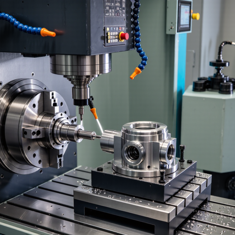
CNC speed and precision are connected, but slower cutting does not automatically produce better parts. Cutting speed, feed rate, and depth of cut affect heat, tool load, vibration, and chip formation. A faster spindle may reduce cycle time, yet it can also heat the tool and workpiece. On a thin aluminum wall, heat can cause slight expansion, so measurements taken before cooling may be misleading. Too little feed can make a tool rub instead of cut, damaging the edge and surface finish. Small changes matter.
The right balance depends on machine stiffness, tool overhang, material, coolant delivery, and workholding. Begin with a stable baseline, then change one cutting parameter at a time. Check dimensions, surface finish, chip shape, and spindle load after each test. A consistent chip and steady sound can be useful clues, but neither replaces measurement. Tool wear may gradually shift part dimensions, even when settings stay unchanged. Measure parts at sensible intervals. Not every result is tidy. A setting that works on a rigid block may chatter on a long, thin feature, and that difference deserves another test.
Before increasing feed or spindle speed, record how the machine and part perform under current conditions. Warm the machine using its normal routine, then note spindle speed, feed rate, tool runout, coolant temperature, and visible vibration. Measure backlash or positioning error if those checks are part of your maintenance process. Keep the setup consistent, including tool, fixture, and workpiece material. On a sample part, record cycle time and inspect critical dimensions with calibrated instruments. Take repeated readings; one measurement can hide variation.
Tips: Measure at the same points each time. Record room and coolant temperatures. Keep a few parts from the run for comparison. A simple table works, even if it is not elegant.
Use this baseline to distinguish machine limits from process choices. If dimensions drift across several parts, check tool wear, clamping, and thermal growth before raising cutting parameters. Compare surface finish and actual cycle time, not just the controller’s displayed values. Change one setting at a time, then repeat the measurements. A small speed increase may look successful until a tool warms up or a long cut shifts the workpiece. Baselines are not perfect; operators may load parts differently, and instruments have limits. Note those uncertainties rather than treating every number as exact.
To raise CNC machining speed without sacrificing accuracy, adjust feed before making a large jump in spindle speed. Higher surface speed can shorten tool life and increase heat, while excessive feed may leave chatter marks or push dimensions out of tolerance. Record the current speed, feed per tooth, depth of cut, spindle load, and tool wear. Then test one change at a time.
For a steel milling trial, increase feed per tooth by about 5–8%, while keeping the toolpath and depth unchanged. Check the cut with a micrometer, inspect the wall finish, and listen for chatter. If the spindle load rises sharply, back off; a clean chip is useful evidence, but not proof of accuracy. ISO 3685:1993 sets a 0.3 mm average flank-wear criterion for many single-point turning tool-life tests. That figure is a controlled test threshold, not a universal shop-floor limit. Tool geometry, coolant delivery, and workholding can shift the safe window. I still find that one setup behaves differently from the next. Keep a short trial log, and stop when the part drifts, not only when the tool looks worn.
Practical starting ranges for milling with a 10 mm, four-flute solid-carbide end mill. Actual parameters depend on tool geometry and coating, workpiece condition, machine rigidity, coolant, and the tool maker’s recommendations.
| Workpiece material | Starting cutting-speed range (Vc) | Starting feed per tooth (fz) | Example spindle speed and table feed | Material-removal strategy | Precision-preserving check |
|---|---|---|---|---|---|
| Aluminum alloys | 300–600 m/min | 0.04–0.08 mm/tooth | At 450 m/min and 0.06 mm/tooth: approximately 14,300 rpm and 3,440 mm/min | Use a sharp, aluminum-suitable tool and steady chip evacuation. Increase feed or step-over gradually while checking for chip recutting and built-up edge. | Check for burrs, chip welding, and heat-related dimensional change; use suitable coolant or air blast. |
| Low-carbon steel | 150–250 m/min | 0.03–0.06 mm/tooth | At 200 m/min and 0.045 mm/tooth: approximately 6,370 rpm and 1,150 mm/min | Use a stable toolpath and moderate radial engagement; raise feed before making large increases in depth of cut. | Monitor spindle load, vibration, and tool wear; confirm dimensions after the first stable pass. |
| Austenitic stainless steel | 80–150 m/min | 0.02–0.045 mm/tooth | At 115 m/min and 0.03 mm/tooth: approximately 3,660 rpm and 440 mm/min | Maintain a continuous cut and avoid dwelling or rubbing. Use a rigid setup and effective coolant delivery where appropriate. | Watch for work hardening, heat, and notch wear; avoid pausing with the tool rubbing against the material. |
| Titanium alloys | 30–60 m/min | 0.015–0.03 mm/tooth | At 45 m/min and 0.02 mm/tooth: approximately 1,430 rpm and 115 mm/min | Prioritize rigidity, controlled engagement, and reliable heat removal. Increase removal rate in small, measured steps. | Check tool wear and temperature frequently; use conservative parameters if chip evacuation or coolant access is limited. |
Calculation: Spindle speed (rpm) = (1000 × Vc) ÷ (π × tool diameter in mm). Table feed (mm/min) = rpm × number of flutes × fz. Example values are rounded and are starting estimates, not guaranteed production settings. Stay within machine limits and verify the tool manufacturer’s data.
Improving CNC machining speed without sacrificing precision begins with the cutting edge, not a higher feed override. Use a sharp, suitable tool with the correct geometry for the material, then limit tool overhang to reduce deflection. Stable chip formation matters: a squeal, polished flank, or uneven chip color can signal heat or vibration. Small gains matter. Adjust speed and feed in measured steps, checking dimensions and surface finish after each change.
Tips: Keep tool stick-out as short as the feature allows, inspect inserts at setup changes, and record stable settings. Do not copy a successful feed rate blindly between machines. Rigidity differs.
Workholding must resist cutting forces without distorting the part. Clean vise jaws and locating faces, add support beneath thin sections, and tighten consistently. Coolant needs to reach the actual cutting zone, especially in deep pockets. Check flow, concentration, and nozzle direction; a strong stream aimed at the tool shank may do little for the chip. More coolant is not always better. Excessive pressure can disturb a delicate setup, while poor chip evacuation can mark a finished wall. Run a short trial and inspect the result.
Illustrative machining trial: cycle time falls as tooling, workholding, and coolant are optimized, while measured dimensional error remains within a 10 µm tolerance.
Example values are illustrative, not universal. Validate cutting conditions and dimensional results on the specific machine, material, and part.
Increasing CNC speed is useful only when dimensions stay within tolerance. In-process monitoring helps operators catch drift before it becomes a batch-wide problem. A touch probe can check a datum or critical feature between operations, while spindle-load and vibration trends can reveal a dulling tool. Small changes matter. A rising load may signal wear, but it can also reflect a different cut or material condition.
Inspection data should guide adjustments, not simply confirm a pass or fail. Compare probe readings with measurements from calibrated instruments, especially for tight tolerances. Check parts at consistent temperatures; a warm component can measure differently after cooling. Record offsets, tool changes, and readings together, so trends have context. Monitoring is not perfect, and a probe can miss surface defects or setup errors. Keep independent checks in the process.
Tips: Set alert limits from actual process capability, not guesswork. Inspect the first part after a speed change, then sample at planned intervals. If readings drift, pause and investigate before raising feed rates again. A little lost time here may prevent costly rework later.
Warm the machine normally. Record spindle speed, feed rate, tool runout, coolant temperature, and visible vibration. Measure a sample part’s cycle time and critical dimensions.
Repeated readings reveal variation that one measurement can hide. Use the same measurement points and calibrated instruments. Keep a few sample parts for comparison.
Try a small feed increase before making a large spindle-speed change. For a steel milling trial, increase feed per tooth by about 5–8%. Keep the toolpath and depth unchanged.
Measure critical dimensions with a micrometer and inspect the finished wall. Listen for chatter and watch spindle load. A clean chip helps, but it does not prove accuracy.
Tool wear, clamping changes, and thermal growth can shift dimensions. Warm parts may measure differently after cooling. Check these factors before raising cutting parameters again.
A touch probe can check datums or critical features between operations. Rising spindle load or vibration may signal tool wear, though other conditions can cause changes. Keep independent inspection checks.
Stop if the part drifts out of tolerance, chatter appears, or spindle load rises sharply. Do not wait only for visible tool wear. Pause and investigate.
Log settings, tool changes, offsets, readings, and actual cycle time. Change one setting at a time. Keep it simple. Measurements have limits, and operators may load parts differently.
How to improve processing speed without losing precision begins with understanding how cutting speed, feed rate, depth of cut, and machine stability affect one another. Establish reliable baselines by measuring machine condition and part dimensions before making changes. These readings help identify current limits and provide a clear way to judge whether faster production still meets the required tolerances.
Increase material removal gradually by optimizing cutting parameters for the material, tool, and part geometry rather than raising speed indiscriminately. Suitable tooling, rigid workholding, and effective coolant delivery can reduce vibration, heat, and tool wear, allowing more consistent cutting at higher rates. In-process monitoring and regular inspection help detect dimensional drift early, so adjustments can be made before defects accumulate. By combining measured trials with stable setup practices, manufacturers can improve throughput while maintaining dependable accuracy.