In 2026, choosing profile drilling and punching tools depends on more than machine price or advertised speed. Material, wall thickness, profile shape, hole spacing, and production volume all affect the result. A thin aluminum channel may distort under a punch that works cleanly on thicker steel. Small details matter. Check tool capacity, stroke, throat depth, locating stops, and machine compatibility before comparing brands. These factors influence hole position, edge quality, operator effort, and repeatability across a batch. How to choose suitable tools for profile drilling and punching starts with defining the actual job, not browsing catalog photos. Record the alloy, profile dimensions, tolerances, and expected output.
Punching can produce consistent holes quickly, but the punch and die must match the material and thickness. Drilling offers flexibility across hole sizes, though bit selection, speed, clamping, and chip removal need attention. Neither method is automatically better. Ask suppliers for clear specifications, compatible tooling options, and guidance on setup and maintenance. Then test a representative offcut. Inspect hole diameter, burrs, profile deformation, and alignment against the drawing. One test is not the whole story. Repeat it under realistic production conditions, especially when profiles vary between batches. A tidy catalog comparison can still overlook awkward clamping or a hard-to-reach hole. Even a careful shortlist may need revision after a practical trial. That is useful information, not a failed decision.
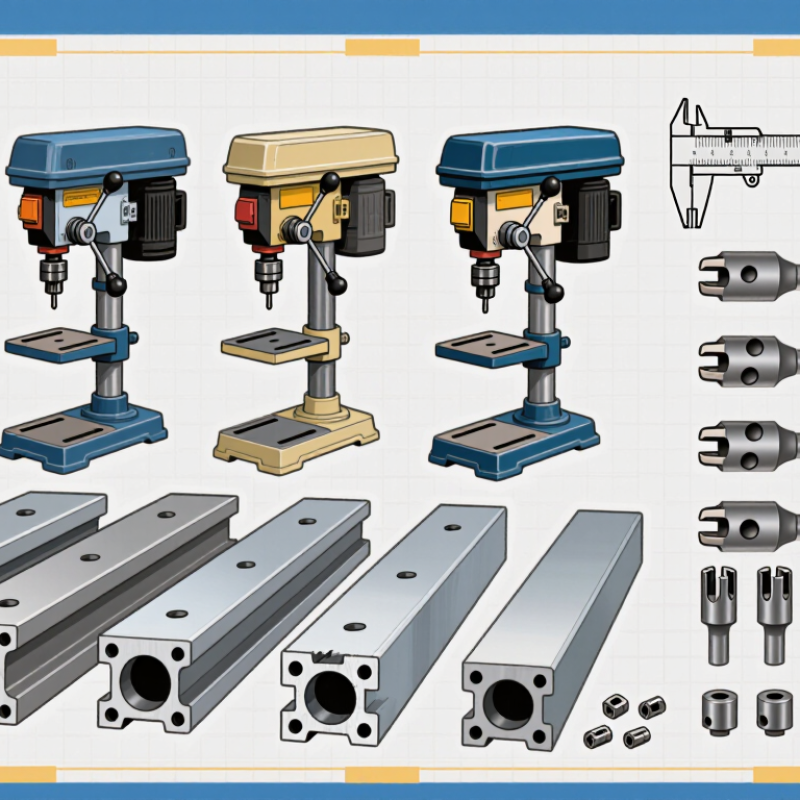
Identify Profile Material, Wall Thickness, and Required Tolerance
Choosing profile drilling and punching tools starts with identifying the exact material, not just calling it “steel” or “aluminum.” Confirm the alloy, temper, coating, and whether the section is hollow. A 2 mm aluminum tube can deform under clamping pressure, while a similar-thickness steel profile may need greater punch force. Measure wall thickness at several points; extrusion corners and welded seams can vary. For context, ISO 2768-1:1989 gives medium-class general linear tolerances of ±0.2 mm for 6–30 mm dimensions and ±0.3 mm for 30–120 mm dimensions. These are not hole-position limits, so use the drawing’s specified tolerances for critical features.
Match tool geometry and clearance to the material and thickness. A drill should clear chips from a deep profile, while a punch needs firm support beneath the wall to limit burrs and distortion. Check hole diameter, position, and edge quality on a trial piece, then inspect the opposite face for breakout. One missed detail: coatings can change friction and tool wear, even when the base alloy stays the same.
Tips: Record actual wall thickness, clamp pressure, and first-piece measurements. If results drift, pause and check tool wear before changing the program. A quick test helps. ISO values are a reference, not a substitute for the part drawing or process validation.
Choose Drill Geometry and Grade for the Material and Cutting Speed
Choose drill geometry before chasing speed. A 118-degree point suits many general-purpose holes; a 135-degree split point can reduce walking on tougher alloys. For aluminum, a polished flute and higher helix help clear long, sticky chips. Brass behaves differently: a lower-helix drill can reduce grabbing. Small details matter. Check the exit side, too; a sharp edge can leave a burr that spoils a formed profile.
Grade must match both the work material and heat at the cutting edge. ISO 513:2012 groups cutting-tool applications by material, including P for steel, M for stainless steel, and N for non-ferrous metals. That is a useful starting map, not a complete tool specification. Machinery’s Handbook cutting-speed tables commonly place HSS drilling in mild steel around 20–30 m/min, while carbide may start near 80–150 m/min. Treat these as trial ranges, not promises. A long overhang, poor coolant delivery, or a thin-walled section may require a lower speed. I have seen the chart win and the setup lose. Record speed, feed, chip shape, and hole finish, then adjust one variable at a time.
How to Choose Profile Drilling and Punching Tools in 2026 - Choose Drill Geometry and Grade for the Material and Cutting Speed
Drilling selection: The speed ranges below are practical starting points in metres per minute (m/min), not guaranteed production settings. Actual results depend on tool diameter, coating, machine rigidity, workholding, coolant, and profile wall thickness. Use the tool maker’s data and adjust for the specific setup.
| Workpiece material |
Suggested drill geometry |
Suitable tool grade |
HSS / cobalt HSS starting speed |
Solid carbide starting speed |
Practical guidance |
| Low-carbon and mild steel |
118°–135° point; standard helix for general work. A split point helps reduce walking. |
General-purpose HSS for flexible setups; cobalt HSS or coated carbide for higher output and rigid machines. |
20–30 m/min |
60–120 m/min |
Clamp the profile close to the hole. Use cutting fluid where suitable and clear chips from deep holes. |
| Austenitic stainless steel |
135°–140° split point; robust web and geometry intended for stainless steel. |
Cobalt HSS or a stainless-rated carbide grade with a suitable coating. |
8–15 m/min |
40–80 m/min |
Avoid rubbing and prolonged pauses, which can work-harden the material. Use steady feed and effective coolant. |
| Aluminum alloys |
118°–135° point with a sharp edge and polished, high-helix flutes for chip evacuation. |
Sharp HSS or aluminum-rated carbide; avoid coatings or edge preparations that encourage built-up material unless specifically designed for aluminum. |
50–100 m/min |
150–300 m/min |
Use lubricant or an appropriate mist where permitted. Prevent chips from packing in the flutes, especially in deep holes. |
| Gray cast iron |
118°–135° point; geometry with a strong cutting edge and reliable chip clearance. |
HSS for lower-volume or interrupted setups; carbide for rigid, consistent production conditions. |
20–30 m/min |
80–150 m/min |
Cast iron is commonly drilled dry; control abrasive dust and follow site requirements for extraction and cleanup. |
| Hardened steel (approximately 45–55 HRC) |
Short, rigid carbide drill with a geometry specifically intended for hardened materials. |
Wear-resistant solid carbide; confirm the grade’s hardness range and the machine’s rigidity. |
Not generally recommended as a standard HSS application |
20–50 m/min |
Use only with suitable tooling, a rigid setup, and the tool maker’s specified speed and feed. Verify material hardness before drilling. |
Punching selection: Punch-and-die clearance is usually specified per side as a percentage of sheet thickness. The ranges below are general starting points; material condition, thickness, hole size, burr limits, and the press setup can change the required clearance.
| Sheet material |
Typical punch tool material |
Typical clearance per side |
Selection and setup notes |
| Low-carbon steel |
Tough, hardened tool steel; select hardness for the press load and production volume. |
About 5–10% of sheet thickness |
Check punch and die alignment. Correct clearance helps balance cutting force, edge quality, and tool life. |
| Stainless steel |
Wear-resistant, tough tool steel; consider a suitable surface treatment for demanding production. |
About 8–12% of sheet thickness |
Stainless steel can require higher cutting force and can work-harden. Avoid dull edges and confirm clearance with the material supplier or tooling specification. |
| Aluminum |
Sharp, polished tool steel; suitable lubrication can help limit material pickup. |
About 4–8% of sheet thickness |
Keep the cutting edge sharp and inspect for aluminum buildup. Confirm the setting against alloy, temper, and thickness. |
| High-strength steel |
High-toughness, wear-resistant tool steel selected for the material strength and press capacity. |
Often about 8–12% of sheet thickness; verify for the specific grade |
Higher strength increases load and tool stress. Confirm press tonnage, tool strength, and clearance before production. |
Calculation reminder: For drilling, spindle speed in revolutions per minute (rpm) = 1,000 × cutting speed (m/min) ÷ (π × drill diameter in mm). For punching, the stated clearance is per side, so total die opening exceeds punch size by twice the per-side clearance.
Set Mild-Steel Punch Clearance at About 5–10% of Thickness per Side
How to Choose Profile Drilling and Punching Tools in 2026
For mild-steel profiles, start punch clearance at about 5–10% of material thickness per side. With 3 mm sheet, that means roughly 0.15–0.30 mm between punch and die on each side. The lower end can produce a cleaner edge in thinner stock, but may increase force and tool wear. The upper end can suit thicker material, though burrs may grow. ASM Handbook, Volume 14B: Metalworking: Sheet Forming, treats clearance as a key factor in fracture and edge quality; the range is a starting point, not a universal setting. Useful, but imperfect.
Check the actual thickness, grade, and condition of the steel before selecting tooling. Then punch a short test run and inspect both the cut face and the slug. A bright, relatively smooth zone followed by a rough fracture zone is normal; a heavy burr signals that clearance, alignment, or tool condition needs attention. Measure clearance on both sides with suitable gauges, rather than assuming the die is centered. For a profile with a narrow flange, support the section close to the hole to limit distortion. Real stock varies, even within one bundle. Record the setting and edge condition, then adjust in small steps; the first result may not be the best one.
Calculate Drill RPM: n = 1,000 × Vc ÷ (π × Drill Diameter)
When choosing profile drilling and punching tools in 2026, calculate spindle speed before cutting. Use n = 1,000 × Vc ÷ (π × drill diameter), where Vc is cutting speed in metres per minute and diameter is in millimetres. The result, n, is revolutions per minute. For a 10 mm drill and a cutting speed of 25 m/min, the calculation gives about 796 RPM. A calculator helps, but confirm the units first.
Vc depends on the workpiece and tool material, so check a reliable machining chart for the specific combination. Then treat the suggested speed as a starting point. A long profile may vibrate, and a thin wall can flex under pressure. Reduce speed if the drill squeals, the chips turn blue, or the hole edge looks rough. Watch the feed, too. RPM alone cannot fix poor chip evacuation or a loose clamp. Small changes matter.
For punching, speed calculations do not replace checking die clearance, punch alignment, and material thickness. A clean test hole in a short offcut can reveal burrs or distortion before the full profile is processed. Real setups are rarely perfect; I would record the final RPM and conditions, then review them when the material or tool diameter changes.
Check Machine Capacity, Tool Alignment, and ISO 2768 Tolerance Needs
How to Choose Profile Drilling and Punching Tools in 2026
Check the machine’s rated capacity against the profile’s material, thickness, and geometry. A machine’s maximum punch force alone is not enough. Confirm its drilling diameter, throat depth, working height, and duty cycle in the technical specification. Test the setup on a scrap piece of the actual profile. Small details matter. A clamp that shifts slightly can move a hole off-center.
Tool alignment affects hole position and edge quality. Check that the drill axis, punch, and die are square to the profile before production. Inspect punch-to-die clearance and support the work near the cutting point. ISO 2768-1:1989 gives general linear tolerances; for class m, dimensions over 30 to 120 mm allow ±0.3 mm, while those over 120 to 400 mm allow ±0.5 mm. Apply these values only when the drawing specifies the standard and tolerance class. Even a careful setup can drift as tools wear, so recheck sample parts during a run.
Tips: Compare the drawing’s tolerance with the machine’s demonstrated repeatability, not just its catalog rating. Record a few measured hole positions after setup. If results vary, pause and inspect alignment, clamps, and tool wear before adjusting the program.
Conclusion
How to choose suitable tools for profile drilling and punching starts with understanding the workpiece and the required result. Identify the profile material, wall thickness, and dimensional tolerance before selecting a drill or punch. Choose drill geometry and tool grade to match the material and intended cutting speed, since these factors affect cutting stability, hole quality, and tool life. For mild-steel punching, set the clearance at about 5–10% of the material thickness per side, then confirm it suits the profile and the desired edge finish.
Next, calculate drill speed using n = 1,000 × Vc ÷ (π × drill diameter), where Vc is the selected cutting speed. Check that the machine can handle the required speed, feed, and force, and verify that the tool is aligned securely with the workpiece. Finally, consider whether the specified dimensions and fit require ISO 2768 tolerance levels, and inspect the finished holes and punched edges to confirm the process meets the drawing requirements.
 Zhixing Machine