 Zhixing Machine
Zhixing Machine
Zhixing Machine
Adjusting machines for different profile sizes and styles is essential for stable production, accurate dimensions, and consistent surface quality. A narrow trim profile does not behave like a wide structural section. Material thickness, geometry, resin or metal grade, and production speed all influence the correct settings. Small errors can create warping, uneven edges, scratches, or excessive waste. These problems often appear after the machine seems properly calibrated.
The key question is: How to adjust machines for different profile sizes and styles without damaging equipment or reducing quality? Skilled operators usually review the tooling, guides, rollers, dies, feed systems, heating zones, cooling units, and cutting settings. They compare the new profile with approved drawings and measured samples. A wider profile may require slower feeding and balanced pressure. A complex style may need additional guide support or a revised cooling sequence. Clearances should be checked with proper gauges, not guessed by sight.
Details matter.
Experienced teams record each adjustment, including temperature, torque, line speed, and dimensional results. This record supports repeatable production and helps identify gradual tool wear. However, no adjustment chart is perfect. Material batches can respond differently, and older machines may show inconsistent pressure or alignment. That assumption can fail. Operators should make controlled changes, inspect the first pieces, and confirm tolerances before full production. Reliable adjustment combines manufacturer guidance, practical experience, documented testing, and disciplined maintenance. It protects both product quality and machine life while allowing different profile sizes and styles to run with fewer surprises.
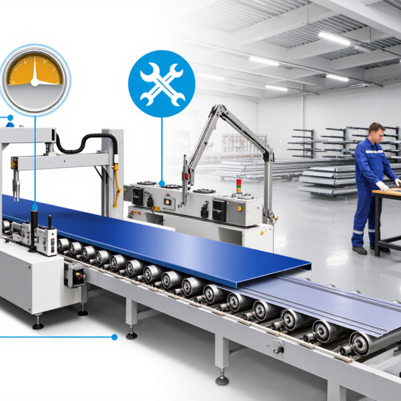
Why Adjust Machines for Different Profile Sizes and Styles?
Understanding profile sizes and styles begins with the product’s physical details. A profile may be narrow, wide, hollow, ribbed, coated, or slightly curved. Each variation changes clamping force, tool alignment, feed speed, and inspection points. A wide profile can flex under pressure. A thin wall can deform before cutting finishes. Small differences matter.
The World Robotics 2024 report recorded 541,302 new industrial robots installed worldwide in 2023. It also reported 4.28 million robots operating globally. More automated equipment means more precise setup decisions. Operators must match tooling, sensor positions, and motion limits to each profile style. A successful setting for a rigid rectangular section may damage a flexible channel. That assumption is often wrong.
Experienced technicians check the first piece closely. They measure width, wall thickness, edge position, and surface marks. They listen for vibration and watch whether material slips during feeding. A useful admission is that setup sheets are not always complete. Profile changes can expose missing measurements or outdated tolerances. ISO 286-1 provides a recognized framework for dimensional tolerances, but real production still requires judgment. The Future of Jobs Report 2023 estimated that 44% of workers’ skills could be disrupted by 2027. Training therefore needs practical adjustment skills, not only software knowledge. Calibration records, sample approvals, and documented corrections make those decisions more repeatable.
| Profile Category | Typical Size Range | Common Profile Style | Primary Machine Adjustment | Typical Feed-Speed Approach | Fixturing Requirement | Main Quality Risk |
|---|---|---|---|---|---|---|
| Small | 10–25 mm outside dimension | Solid or thin rectangular section | Use reduced clamping force and smaller tooling where applicable | Moderate to high, depending on material and wall thickness | Close support with soft contact surfaces | Deformation, slipping, or excessive burrs |
| Medium | 26–60 mm outside dimension | Square, rectangular, or moderate-wall hollow section | Set tool alignment and clamping pressure to maintain profile geometry | Medium feed rate with stable chip or swarf evacuation | Two-point or multi-point support is commonly suitable | Dimensional variation and uneven cutting |
| Large | 61–120 mm outside dimension | Large rectangular or heavy-wall hollow section | Increase support area and verify machine clearance before production | Lower feed rate to control cutting load and vibration | Rigid supports and distributed clamping are recommended | Vibration, deflection, and out-of-square cuts |
| Round | 20–100 mm diameter | Solid round or round tube | Use V-blocks, collets, or shaped jaws to prevent rotation | Adjust according to diameter, wall thickness, and tool engagement | Anti-rotation support is essential | Rotation, ovality, and inaccurate hole or cut location |
| Thin-Wall | 0.8–2.0 mm wall thickness | Hollow tube or lightweight formed section | Reduce clamping force and use sharp, properly supported tooling | Controlled feed rate with gradual tool entry | Internal mandrel or close backing may be required | Crushing, tearing, and edge distortion |
| Complex | Multiple cavities or features | T-slot, ribbed, channel, or asymmetric section | Create a dedicated fixture and confirm toolpath clearance around projecting features | Start conservatively and optimize after test cuts | Profile-specific locating points and anti-twist support | Feature damage, misalignment, and incomplete machining |
Profile size changes contact points, cutting load, feed resistance, and surface-mark risk. A setting for thick stock may distort a narrow profile.
Measure wall thickness, hardness, moisture, width, and surface finish. Check several points along the profile, not only the end. Small differences matter.
Adjust the guides until the material stays centered without force. Excess pressure can bend soft stock, increase heat, or leave marks. Clean away dust first.
Match the tool to the material, thickness, curve, and finish requirement. A narrow cutter may suit a detailed edge. A wider guide can support broad sections.
Begin with a test piece and a shallow first pass. Increase speed or depth gradually. Stop if the material twists, overheats, or develops uneven edges.
It may signal excessive load, weak support, or a dull cutting edge. The sound is useful, but it is not proof by itself. Inspect the setup.
Measure several consecutive pieces with suitable gauges. Check dimensions, alignment, surface finish, burrs, whitening, and corner shape. One good sample proves very little.
Record speed, pressure, temperature, tooling, material moisture, and inspection results. These notes improve repeatability. Still, I once trusted an old setting too much. A short trial would have exposed the problem.
Different profile sizes and styles require careful machine adjustments to maintain accuracy, efficiency, and consistent results. Profile dimensions can influence alignment, pressure, speed, cutting depth, feeding stability, and overall machine performance. Understanding the shape, thickness, length, and material of each profile helps operators determine the correct setup before production begins. Knowing How to adjust machines for different profile sizes and styles is essential for reducing errors, preventing unnecessary wear, and achieving reliable output.
Adjustment may involve repositioning guides, changing tools, setting rollers, modifying feed rates, and selecting suitable pressure or temperature levels based on the material and profile requirements. After making these changes, operators should verify measurements, alignment, surface quality, and machine stability through careful testing. Safety checks are also important, including confirming that guards are secure and controls function properly. A final inspection ensures that the adjusted machine produces profiles that meet dimensional, performance, and quality expectations.
